 An ongoing question on many Arduino forums is how to modify software to suit the different types of matrix modules available. Usually the poster has tried some LED matrix software and the display is reversed or upside down, or animations are disjointed across the module boundaries.
There are clear reasons this happens, and the Parola library has software configuration parameters that allow you to adapt how the software operates to suit your hardware module.
Why is there a problem?
The first thing to understand is why there is a problem at all.
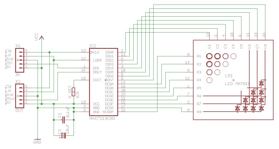
The MAX7219 and MAX7221 control ICs were originally designed to control up to 8 digits of 7 segment display. Each digit has 7 LED segments (named a to g) and a decimal point (dp) connected through a common cathode. The IC multiplexes the display of the segments sequentially across all the digits to be displayed.
Basically, the IC capable of controlling 64 individual LEDs (8 digits x (7 seg + 1 dp)) and there are 64 LEDs in a LED matrix.
However, unlike the mapping to digits/segments, there is no standard mapping of the 64 LEDs to matrix rows and columns. So there are a number of hardware configurations that can (and do!) result, depending on how the hardware designer has wired up the MAX7219 to the LED module:
- ‘Rows’ can be wired as ‘digits’ or ‘segments’ increasing left to right or right to left
- ‘Columns’ can be wired as ‘segments’ or ‘digits’ increasing top to bottom or bottom to top.
So, any matrix can be physically wired so that the matrix orientation (in physical space) can have rows or columns in either direction and in any order. This means that writing a library like Parola, where the code must assume a standard coordinate system for it to work, requires a mapping between the physical pixels (LEDs) and this standard coordinate system.
A Brief Word on Coordinate Systems
Two Cartesian coordinate systems are used in the library. One defines the pixels seen (display coordinates), and the other is an underlying hardware coordinate system based on digits and segments mapping to the MAX72xx hardware control registers.
In Parola, display coordinates always have their origin in the top right corner of a display and by convention
- Column numbers (and therefore module numbers) increment to the left
- Row numbers (0..7) increment top to bottom
All user functions consistently use display coordinates to make animations independent of underlying hardware changes. It is the job of the hardware control library functions to map display coordinates to hardware coordinates.
Adapting the Library
The coordinate system mapping is a function of the hardware library (MD_MAX72xx). From the above discussion, the hardware library needs to know if
- ‘Digits’ are mapped to rows or columns. This also fixes ‘segments’ to the other axis.
- The order in which each axis is wired (up/down and left/right). A simplifying assumption (which has been valid so far!) is that the LEDs are wired sequentially and not in random order.
The MD_MAX72xx library needs to be informed of the the following parameters to direct the hardware coordinate mapping:
- HW_DIG_ROWS – set to 1 if MAX72xx digits are mapped to rows in the matrix
- HW_REV_COLS – set to 0 for normal orientation with col 0 on the right, set to 1 if reversed
- HW_REV_ROWS – set to 0 for normal orientation with row 0 at the top set to 1 if reversed
In practice, there seems to be four common types of matrix modules on the market, and so it is convenient to define ‘canned’ combinations for those matrix types:
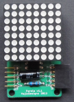
- Parola style modules that are now manufactured as kits by ElectroDragon. The library was originally developed for this module type.


- Generic Modules commonly available from many suppliers (eg, eBay) at reasonable cost. They are characterized by IN and OUT connectors at the short ends of the rectangular PCB.


- ICStation kit module available as kits from ICStation.


- FC-16 modules identifiable by the FC-16 designation silk-screened on the PCB. Many of the ‘4-joined-up’ module systems are made up of individual FC-16 modules.


In MD_MAX72xx prior to version 3.0.0, the type of module being used for the library is defined by editing the appropriate #define in the MD_MAX72xx header file. For most users, this was be the only action necessary if they always used the same type of display module.
From version 3.0.0 onwards, the module type is specified in the application as one of the parameters to the class constructor. This eliminates the need to edit the library header file for the different module types.
Determining New Hardware Configurations
The library example code includes a utility called MD_MAX72xx_HW_Mapper. This test software maps display hardware rows and columns. It uses a generic SPI interface and only one MAX72xx/8×8 LED module is needed for testing.
It is independent of the libraries as the code is used to directly map the display orientation by setting pixels on the display and printing to the serial monitor which MAX72xx hardware component (segment and digit) is being exercised.
By observing the LED display and the serial monitor you can build a map like the one below. It is worth noting the direction in which the rows and columns are scanned by the utility, as this is the easiest way to work out the row/column reversal values.
The result of these observations is a grid definition that looks somewhat like:
DIG0 D1 D2 D3 D4 D5 D6 D7
Seg G
Seg F
Seg E
Seg D
Seg C
Seg B
Seg A
Seg DP
From this example mapping it is clear
- MAX72xx digits map to the columns, HW_DIG_ROWS is 0.
- DIG0 is on the left (columns were also scanned left to right), so HW_REV_COLS should be set to 1 to reverse it to the standard 0 on the right.
- Seg G is at the top (rows were also top to bottom), so HW_REV_ROWS should be set to 0, as it is already standard with 0 on top.
Note that in some situations using the module ‘upside down’ will result in a better configuration than would otherwise be the case. An example of this is the generic module mapping. Also remember that the modules are daisy chained from right to left.
Having determined the values for the defines, the mapping can be matched to an existing hardware type or a new type defined.

48 replies on “Parola A to Z – Adapting for Different Hardware”
Hi, thank you for your wonderful library. I want to ask your advice on if it is possible to have mixed type of HW ? I have some old Generic modules and some newer FC16 modules. I have tested that they can daisy chain but the Generic ones will be mirrored from the FC16 ones.
LikeLike
All the modules in one connected string need to be the same type.
LikeLike
[…] other types You will get letters rotated or in wrong order. If You have some other, custom module here You can read how to customize library for Your […]
LikeLike
[…] dość losowa a napisy nie będą przez to czytelne. Jeśli masz jakiś mocno niestandardowy moduł tutaj znajdziesz info jak skonfigurować nietypowe […]
LikeLike
A newbie question.
I want to make a clock, but I would like to be able to change hardware type (ex. #define HARDWARE_TYPE MD_MAX72XX::ICSTATION_HW) via a web interface.
Is that doable or do I have to precompile all combinations of hardware and no of LED modules?
LikeLike
Hardware type is dynamic and can be changed at run time. You need to use the MD_MAX72xx method setModuleType(). Get a pointer to the MD_MAX72xx object used by Parola using the Parola getGraphicObject() method. More information can be found in the libraries documentation.
LikeLike
Thx, then it would be quit easy to make a hardware test program to test what HW module you got. Thx again for your quick reply and now Im rolling up my sleves and at it.
LikeLike
Look at the MD_MAX72xx example MD_MAX72xx_Dynamic_HW
LikeLike
Ok, I have figured it out and have a work in progress.
Could you give me a pointer to how to dynamically change number of devices, I found “getDeviceCount” but theres “setDeviceCount”?
LikeLike
You need to recreate the object to change the number of modules. This cannot be done “on the fly” like for module type. This will probably mean that you cannot declare the whole object as a global static but will need to use new() and delete() to make and destroy the object dynamically.
LikeLike
Thx, that did it. I really appreciate your help!
LikeLike
[…] display.https://github.com/MajicDesigns/MD_MAX72XXParola 8×8 dot-matrix display hardwarehttps://arduinoplusplus.wordpress.com/2017/04/14/parola-a-to-z-adapting-for-different-hardware/Arduino PIN definities en […]
LikeLike
[…] type hardware is gebruik voor de display. Voor de A-Vision ESP8266 learning board project is de Parola type hardware gebruikt.We moeten natuurlijk ook zorgen dat de software voor het aansturen van de display […]
LikeLike
[…] type hardware is gebruik voor de display. Voor de A-Vision ESP8266 learning board project is de Parola type hardware gebruikt.We moeten natuurlijk ook zorgen dat de software voor het aansturen van de display […]
LikeLike
Hello, I made a custom display using eight vintage 5×7 modules (TIL305) connected to eight MAX7219. Since there are three columns and one line missing on each display, I get incomplete characters. Is it possible to customize this library for 5×7 displays?
LikeLike
Technically yes but I would expect that there will be a lot of code changes to make it work. There are a couple of #defines for the number of rows and columns in the display that will give an indication of where things will need to change, but I also suspect that there will be assumptions in other places that are implicit.
LikeLiked by 2 people
Hi how would I include the instructions used in the article To my sketch? Sorry I’m new
LikeLike
Look at the examples that come with the library. You will need to tell the library what type of module you are using in your sketch.
LikeLike
Hi so your saying that the instruction such as HW_DIG_ROWS SHOULDNT be adjusted outside the sketch. Only orientation adjustment should be made by changing The hardware type. Is this correct? Thank you for your hard work.
LikeLike
For 99.9% of people just selecting the hardware type will be sufficient. For those that create an new hardware configuration, they will need to change things in more detail. FYI there has not been a new hardware type needed since 2015.
LikeLike
Can anybody tell me how to increase text in Parola_Scrolling sketch please? I am new to this.
LikeLike
Please explain what you are trying to do.
LikeLike
Hi Marco, I want to display 2 or more chapters of the gospel of John, using 4 units of dot matrix, how I increase the amount of text using Parola Scrolling sketch please?
Anderade
LikeLike
The size of the serial buffer is defines by #define BUF_SIZE 75, so to make more characters you will need to make this bigger. I would think that 2 chapters of the gospel will take more memory than you have in the arduino so you may be better thinking about storing that in an SD card and displaying the text from the SD card.
LikeLike
Thank you Marco the Lord Jesus Christ blesses you always.
Anderade
LikeLike
Hi Marco
I did increase the #define BUF_ SIZE 450 and it is accepted by the Parola_Scrolling.
Now I loaded 330 words and it was accepted too, meaning accepted by the memory.
The message displayed was only 92 words. What can I do to make the 331 words display, especially the programme is okay with this load of words.
Thank you
LikeLike
450 is the number of characters it will display. I don’t think this can be 330 words so something you are telling me is not correct. If you want more technical assistance then please raise an issue in the Parola thread of arduino.cc at https://forum.arduino.cc/index.php?topic=171056.0 as this is not the best place.
LikeLike
Thank you Marco, I will do what you asked me to do. Thank you again for help.
Anderade
LikeLike
Sorry, does not work for me, not any of the examples, even with the correct pins and all existing hardware profiles…
LikeLike
Interesting. There have been tens of thousands of downloads an yours is the first that does not follow a pattern. You may have a new type of hardware. Raise the issue on the Parola thread at the Arduino forum (http://forum.arduino.cc/index.php?topic=171056.1455) and we can try and solve the issue.
LikeLike
For MAX72xx library or MD_Parola here are the solutions that work with the led modules:
Just open the example, and if it is not working or mirrored … just change the headers for one of this:
#define HARDWARE_TYPE MD_MAX72XX::FC16_HW
#define HARDWARE_TYPE MD_MAX72XX::GENERIC_HW
#define HARDWARE_TYPE MD_MAX72XX::ICSTATION_HW
You can just change it and compile with one of those lines each time … or just take unplug one 8×8 module and check the name on the board below the chip …. if it says FC16 is FC16 … if it is ICstation it should work with the ICSTATION
THIS SOLUTION WORKS using Arduino 1.8.8 with the MAX72xx library version 3.0.2. If the device is not a max7219 this library will not work. If the max72xx library is before version 3.0.2 you need to edit the library header files or upgrade to the newer version.
LikeLike
Thanks for your contribution. Identifying the LED modules is covered in the MD_MAX72xx library documentation and is usually pretty easy. I would also encourage everyone to upgrade to the latest version of the library and find and read the library documentation that is in the docs folder of the library install.
LikeLike
What worked for me was to change:
#define HARDWARE_TYPE MD_MAX72XX::FC16_HW
to:
#define HARDWARE_TYPE MD_MAX72XX::ICSTATION_HW
But can anyone suggest why the last string character does not activate all leds until scrolling occurs after the delay?? Than all light up and scroll as expected. Thanks.
LikeLike
Awesome work! Thanks.
LikeLike
Hi Marco,
Thanks for the library but I have two questions:
1. Where did you get the info that the MAX7221 is for use with common anode displays?
The datasheets states:
The MAX7219 and MAX7221 are identical except for two parameters: the MAX7221 segment drivers are slew-rate limited to reduce electromagnetic interference (EMI), and its serial interface is fully SPI compatible.
They also mention a difference in behaviour of pin 12 (Load data/ chip select) but there is no mention of common anode use.
2. Can you advise on the best way to modify the library for use with 8 rows x 5 cols matrix displays instead of 8×8 displays?
Thanks,
Mario
LikeLike
You are correct that the 7221 is the same. Article has been amended.
What needs to be done depends on your hardware. If is is not MAX72xx then I would find a different way to do this. If is is MAX72xx then you will need to restrict the active ‘digits’ in the hardware (scan register) and also ensure that the module boundary calculations are correct as you now have to divide by 5 rather than 8. This could be as easy as changing a constant but I doubt it.
LikeLike
Thanks for the advice.
I have a bunch of 8×5 matrix units so I’m looking for a way to use them.
There is no controlling hardware connected so I think I will go for the MAX72xx option and try to get the code working.
LikeLike
Hi marco_c
I wasted almost 1 week researching on how to fix the mirrored letters on 32*8 LED matrix using Parola library. Every talks about making parameter (USE_PAROLA_HW or USE_GENERIC_HW) changes in MD_MAX72xx.h. No one has provided the explanation as you have provided. Suggestion to use “Determining New Hardware Configurations” is excellent and should resolve the problem. Will try out and update this post if issue is resolved.
LikeLike
Sorry it took you so long to get to the info. Similar info is available in the information supplied with the libraries and there is a clear warning on the github site README file that the modules need to be configured in the library.
Worst case you can just try each of the module types in turn. Nothing will get damaged – you will just see various permutations of incorrect behavior.
If you get no joy, tech support is easier in the Arduino forum at http://forum.arduino.cc/index.php?topic=171056.0
LikeLike
Hi i have this same problem. REVERS letters, and i use FC16_HW orginal is PAROLA_HW
LikeLike
hi,
Your work very cool! I have a question,Does parola lib supportot this 32 64 led?
https://www.embeddedadventures.com/led_matrix_display_LDP-6432.html
LikeLike
No, these panels are not supported as they are not controlled by the MAX7219 or MAX7221 ICs.
LikeLike
thanks,those panels controled by 74h138 and 74h595. If I use 7219,32*64 needs 32 8*8led matrix.
the question is parola lib supported so many led matrix?
LikeLike
Yes it can support that many. So users have used up to 40+ in a row. However, this is on/off (single color) control only and not tri-color.
LikeLike
Hi Marco, First off thank you very much for creating these amazing library / module for the arduino. I’m not really sure what to call it but I thank you greatly. I just want to reach out to you to see if you can help me with the problem I encountered running other examples in the MD_MAX79xx. I can only run the test example. Other examples is not running correctly. I get garbled text in serial when running the print message example. I don’t have the arduino with me right now but I might be able to send pics later…
LikeLike
Check that the speed setting on Serial Monitor is the same as the Serial.begin() code in the Arduino software.
LikeLike
Thank you again Marco. Why is it always the obvious mistakes are the one hard to resolve… Anyway, I got the MD_max72xx_printTest working. I just have another question regarding fonts. How can I use the sys_var_double font? I did run the txt2font and it produced a h file for sys_var_double but for the life of me I can never figure out how to use it in the printTest example. I have read the md_max72xx h file as well as the library but I can’t make or do not understand how to change font to sys_var_double. Can you please direct me to either an example or a discussion where this came up before? I have been searching the internet and I can’t find an example using this font.
Again, I appreciate your help on this matter and I thank you greatly for your contribution and help to a fellow like me.
LikeLike
The double height font is for double height displays. There is an A to Z article on working with double height displays and there are a bunch of double height examples to look at.
LikeLike