 After many years persevering with a ‘simple’ soldering iron, I acquired a temperature controlled iron and was amazed at the difference it made to the quality of my work. Recently the iron failed and, although I managed to find the fault and repair it (the temperature sensor wire had broken off), it made me realize that I should keep one as a spare. It is actually quite difficult to repair an iron without an iron!
As I can’t afford to buy an expensive piece of equipment ‘just in case’, I decided to use this as an excuse for a hardware and software project based around a Hakko-FX888 soldering handpiece that I had already purchased.
Requirements
I had a few requirements for what I wanted to make:
- Temperature Controlled. The iron needs to provide good temperature regulation, preferably using the PID control algorithm.
- Compact and light. This iron will spend most of its time stored away and will become the transportable option should I need to use an iron away from my bench.
- A small character based LCD Display to show current values, settings and to set parameters.
- Simple User Interface and menu system to access
- Uncomplicated Controller Circuit that could be controlled from an Arduino Pro Mini.
As with most projects, I started with a search of the internet so that I could ‘stand on the shoulders’ of others. DIY soldering irons are a popular project and I soon settled on a number that were likely candidates. The final design I implemented was mainly based on this design, which met most of my criteria.
Basic Soldering Iron Design
A temperature controlled soldering iron is basically just a heating element and a temperature sensor for feedback. To control the temperature, the system is continuously monitoring the error difference between the set point (the target temperature) and the current value (the actual temperature). This error is used to decide how to adjust the heating applied by the iron, in our case using an Arduino micro controller via PWM.

A common method for doing this is to use PID (Proportional-Integral-Derivative) control algorithm to do this. There is a lot of information about PID on the internet – one of the best explanations I have read for micro controllers is this series of blogs. The PID algorithm is based on the formula
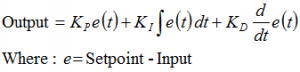
The three K parameters have the following meaning
- Kp is proportional to the error at the present time.
- Ki accounts for errors that have accumulated (integrated) over time.
- Kd is a prediction of future error based on the trend (slope) of the current value. Kd is often not used during aggressive PID, especially when initially driving to the set point, at which time a more conservative control regime using Kd can take effect.
Controller Hardware Design
 The iron controller is based on the original design with changes to accommodate the LCD display. The high level block diagram for the project breaks it down into its major components:
- Arduino Pro Mini to manage the system.
- Temperature sensor amplifier for the relatively small analog signal read from the iron.
- Power control for the resistive heating element
- Character based LCD display (1602 in this case).
- Rotary encoder with built-in switch.
- A switching power supply (24V 6A, like this one on eBay)

The Schematic and PCB design in Eagle CAD format are available here.
The circuit schematic is straightforward and is mostly described in the source design. The power control elements center around the IRFZ44N MOSFET connected to a PWM pin on the Arduino Pro Mini. The output from the PID calculation (0-255) directly drives the PWM output.
An LM358 OpAmp is used to amplify the signal from the sensor. The trimpot R2 is used to set a reasonable value for the analog input during calibration (more on that in Part 2).
 The Arduino Pro Mini, amplifier and LCD require a +5V interface. During the design I assumed this voltage would be supplied externally, as I was concerned that the usual LM705 based power supply would be really inefficient and create too much heat dropping 24V to 5V. It was only after the PCB was made that I found a tiny buck converter on eBay that would do the job really efficiently. The DSN-Mini360 buck converter is specified with input 4.75V to 24V and adjusted output 1V to 17V at 1A. You can just see it mounted to the back of the PCB, poking out from the edge of the fully populated board below. The output of the buck converter needs to be adjusted to 5V before it is connected to the board to avoid damaging the Pro Mini and LM358.
The LCD interface is for a two-wire SR piggyback board (details here). This can be easily changed to a more common I2C interface if required.
The PCB was designed to be single sided so that it could be made easily on my CNC setup.


Once populated, the board was complete and ready for calibration, and testing with the software, which will be covered in Part 2.


22 replies on “DIY Soldering Station with Hakko FX-888 Iron – Part 1”
I become very interested in this project since i already built one soldering iron controler but this looks way better than mine. So i carefully read this and saw the diagrams. I also took a quick look at the code and i think there is an error on the schematic. The schematic on part 1 shows the output from the LM358 going in to pin A3 of the Arduino. But the sketch in defines the input as A0 (and the layout of the board connects to A0 also.
I will try to convert it to I2C comunication with the LCD (far more common than the shift register used here) and see if i can make it work.
Anyway: GREAT PROJECT
LikeLike
Thank you for the answer!
What can be changed to work with a thermocouple.
I want to use a soldering iron from Luckey 702
LikeLike
You will need to change the code that reads the temperature sensor to work with a thermocouple instead of just a simple resistance. Not sure what that is as I have not used thermocouples. The current sensor is just a reading from 0-1024, read using the class called ResponsiveAnalogeRead, so that should give you somewhere to start investigating.
LikeLike
Is this an input for a thermocouple or a thermo-resistance?
My soldering iron has a thermocouple, can I use this circuit?
LikeLike
This circuit is for a resistive input.
LikeLike
This is cool!
LikeLike
Hi. Marko.
Super project. Is it possible to connect a Weller LR21 soldering iron? The resistance of the sensor is 22 Ohm and the 12 Ohm heater? This sensor seems to be PTC.
LikeLike
Intheory I guess this is possible. What may need to change is the ‘interface’ hardware that is on the controller. I have not done this so I would not be able to comment with any intelligence.
LikeLike
Hi,
I have etched the PCB and assumed that my two wire LCD I2C with 8574 chip (common one as you call them) will work but I am having problems with it. There is nothing on the screen. The Atmega chip is “hardwired” for A4 and A5 output to I2C LCD and usual example files work with my I2C board. They do not work connected to D8 and D9. As soon as I change the CLCK And Data pins (from A4-A5 to D8-9) of course it does not work. I even tried to mess around in your Hardware.h file. That did not work either.
Could you please tell me how to modify the code so I can use the I2C two wire boards or tell me which particular SR piggyback board did you use? You say it is easy but I am banging my head for a week now with no results. In the link provided for the SR piggyback board some Shift Register design links are not working as well which does not help.
Thanks.
LikeLike
Have you changed the LCD software object to use the I2C version instead of the SR version? The hardware change needs a similar software change. The software only needs to change in the object instantiation and initialisation, the rest should be ok.
LikeLike
Thanks for replying.
I commented out the:
//#include and added the:
#include and:
LiquidCrystal_I2C lcd(0x3F);
If that is what you mean, but no joy.
LikeLike
I would also think that you should eliminate the pins definitions for SR as these may be used initialised somewhere. Do you also need to include the Wire.h header file?
LikeLike
I ran into this same issue when I made mine. I ended up just removing a lot of the code and using only the temp controlling PID controller portion since changing every aspect of the display to be I2C would have taken many hours to do.
LikeLike
@Marco:
Wire.h does not make any difference. I get the same amount of warnings with or without it.
I bought some 74HC595 (20 of them for a 99p) and I will try the Two Wire backpack from the link in the article. The quick breadboard did not work last night but I must have been tired. I will try again tonight.
@J Anderson:
The NewLiquidCrystal library is apparently 40 times faster than the “ordinary” LCD library. I did not see that as yet on account it does not work for me. But I am hopeful. If it does not work I will have to revert to a simpler code.
LikeLike
Are you getting errors or warnings? Does it actually compile?
In principle, to change from SR (or any other variant of LCD) to another is just a matter of including the right header file and changing the initialisation of the object. I regularly change between LCD shield to SR, and I2C should be no different. All the other functions to manage the LCD object remain the same, so I am not sure why this is complicated.
LikeLike
Hello Marco,
Thanks much for this write up. I plan on making one of these myself and appreciate that you have done some work before me.
What is the inductor for? Everything else makes sense but you don’t mention the purpose of this part.
-Jon
LikeLike
The purpose is described in the original article referenced under the heading “Minor Schema Change” towards the end. It basically absorbs the energy stored in the soldering iron coil when it is switched on and off. It protects other components from over voltage.
LikeLike
That makes sense. Could another option of trying to protect against this be either another diode (like you have with 1N5408) or perhaps like effective a Zener diode that goes directly to ground if the voltage goes past the desired amount.
LikeLike
Not sure as I am not an electronics expert. As far as I know, the energy is absorbed by inducing a magnetic field, which may not be the same if you replace the inductor with a diode.
LikeLike
Got it. I assume that since there is a diode in the MOSFET you used that another method of voltage suppression isn’t necessary and if so, another diode would probably be fine.
Thanks for the explanation. I’m just trying to understand electronic fundamentals more as I go along. I appreciate your blog!
LikeLike
Great project Marko. Any chance of doing a post on your CNC machine that you used to fabricate the PCB ?
LikeLike
Thanks Peter, credit also to the original project this was based on. The CNC machine is a ShapeOko2 with TinyG controller. I wrote a bit about it in some of my early posts.
LikeLike